Hoe word 'n gesmede nokas vervaardig?
Manufacturing a gesmede nokas requires more than simply forming a steel bar into the general shape of a camshaft. The finished component has to combine a sound metallurgical structure with accurately machined lobes, journals, oil passages, and other functional features. Because the camshaft operates continuously inside an engine and is exposed to repeated contact loads, rotational forces, and friction, every stage of production has a direct effect on its final performance. The manufacturing route normally begins with alloy steel selected according to the required strength, hardness, wear resistance, and heat-treatment response. The steel is cut into billets, heated to a controlled forging temperature, and progressively formed using dies and high-force forging equipment. After forging, the component is heat-treated and machined to achieve the required dimensions and surface characteristics. Depending on the design, additional surface hardening and finishing operations may also be required. For a manufacturer, the challenge is to control the entire production chain rather than focusing only on the forging operation. Material quality, forging temperature, die design, cooling, heat treatment, machining accuracy, surface hardness, and final inspection all have to work together. The following sections explain how a forged camshaft is manufactured from steel billet to finished engine component.
How does the manufacturing process begin?
Selecting the steel and preparing the billet
The first step is material selection. The camshafts are made from a variety of alloy steel grades, based on the engine type and the mechanical and surface attributes desired. The material required to have an appropriate combination of strength, toughness, hardenability, and resistance to repetitive contact loading.
The material specification is defined, and then the steel is cut into billets of controlled dimensions. Billet weight is crucial because too little material can leave the die incompletely filled while too much creates flash and material waste. Hence, the billet dimensions must be kept constant during production in the cutting process.
Then the billet is heated to a temperature sufficient for hot deformation before forging. There is no common temperature value; it is determined by the steel grade, the billet size, the forging equipment, and the selected process path. Many hot-forging applications may heat the material to approximately 1,000°C–1,200°C, but the actual production window should be decided based on the material and process factors.
The heating has to be uniform too. Large temperature differences in a billet might cause non-uniform deformation and possibly undesirable metallurgical conditions. This is why regulated furnaces and proper temperature monitoring are crucial features of the preparation cycle.
Designing the preform and forging sequence
The geometry of a camshaft is quite complicated in that the lobes and journals are dispersed on one shaft. Trying to create the complete shape in one deformation step may lead to bad material flow or partial die filling. Manufacturers typically design a forging sequence to move material incrementally to the desired shape.
The first process can result in a preform, which distributes the heated steel along the length of the component. Later forging operations then create the main shaft elements, lobes, journals, and other characteristics. The exact order is determined by the design of the camshaft and the capacity of the forging machine.
This is a very significant point for the design of the die. The dies must offer a regulated flow of material with sufficient allowance for future machining. Flash may form near the die separating line and is usually eliminated during forging. Good die design also helps prevent needless movement of material and enhances consistency from cycle to cycle.
What happens during camshaft forging?
Forming the heated steel under controlled pressure
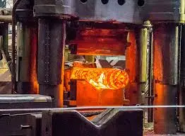
After heating, the billet is transported to the forging machinery, still in the correct temperature range. Depending on the production needs, hydraulic presses, mechanical presses, or other forging systems can be employed.
During deformation the steel would flow into the die cavity and gradually take the necessary geometry. The forging force should be enough to fill the die for a gesmede nokas, but not so much as to cause difficulties of severe deformation. The workpiece temperature must be maintained within the required process window at the same time.
One of the important advantages of forging is the formation of a desirable flow pattern of the metal. The forge does not merely pour molten metal to make a part; it plastically deforms solid steel. With good management of the sequence of forging and of the reduction, the flow of the material can be made to follow key parts of the component. This is why forgings are so often considered for situations where fatigue resistance and structural integrity are of importance.
The forged shape usually does not correspond to final machined dimensions. Critical surfaces have been purposely left with extra material so that subsequent machining operations may remove it and define the final geometry.
Removing flash and controlling the forged shape
Excess material near the die separating line can require trimming after the primary forging operation. The flash is removed by the trimming operation to produce a more manageable forged blank for the following operations.
At this point, producers may additionally check the forging for apparent faults, dimensional variations, or other anomalies. The benefit of early inspection is that if an issue is found before significant machining is done, further processing expenses on a nonconforming product are avoided.
After forging, the cooling also needs to be managed. Depending on the material and production process, the forged camshaft may be subject to controlled cooling, normalizing, or other thermal treatment before further operations. Not all forged camshafts need to be quenched rapidly. The correct cooling and heat-treatment procedure should be adopted according to the steel grade and the qualities required.
How is the forged blank heat-treated?
Establishing the required microstructure
The heat treatment is an important step, because the mechanical qualities of the camshaft are not just determined by the forging process. The material specification and the combination of hardness, strength, toughness, and machinability required dictate the choice of heat-treatment technique.
Depending on the manufacturer’s requirements, methods can include normalizing, quenching, tempering, stress relieving, or other controlled heat treatments. Upon forging, normalizing can be used to refine and homogenize the structure. When a certain mix of hardness and toughness is desired, quenching and tempering can be utilized.
The temperature cycle has to be well managed. The resulting microstructure can be affected by overheating, keeping at the wrong temperature, or cooling inappropriately. Manufacturers therefore need proper furnace controls and verifiable process parameters.
Preparing the component for machining
Dimensions can also be affected by heat treatment. Thermal processing of a forged camshaft can cause modest quantities of distortion or dimensional change, particularly where portions of various diameters cool at different rates. For this reason, machining allowances and process sequencing are incorporated in the initial forging and component design.
If required, stress-relieving treatment can be applied to eliminate residual tensions prior to precise machining. The goal is to produce a stable component that is able to keep its dimensional correctness during the next steps of manufacture.
How does precision machining create the final camshaft geometry?
Rough machining and datum preparation
The blank is still oversized after forging and heat treatment. Thus, rough machining is done to define reference surfaces and to efficiently remove material before final operations.
The main shaft diameter and the journal regions can be set by turning operations. Other machining techniques can provide centers, shoulders, oil channels, keyways, or other design characteristics. It is critical at this phase to establish correct datums, as subsequent CNC work depends on good reference points.
Machining allowances should be handled carefully. If you leave too much material, the finishing process is not efficient. If there is not enough left, there may not be enough stock to make up for distortions from heat treatment or forging variation.
CNC machining of journals, lobes, and oil passages
The CNC machining allows for the dimensional control for the final geometry of the gesmede nokas. The production specification and engineering drawing can be used to program computer-controlled turning, milling, drilling, and other operations.
Cam lobes must be controlled with great care. The shape of the cam lobes controls the movement of the valve train. The lobe shape determines the valve lift, opening and closing characteristics, and the rate of acceleration of the valve train. Therefore, the machining process must copy the given profile correctly and not just make a shape that looks similar.
The journals are also machined to controlled sizes and surface finishes so that they can work correctly with the associated bearing surfaces. Oil holes and internal channels can be drilled or machined as dictated by the lubrication design of the engine.
Modern CNC equipment can maintain tight dimensional tolerances, but the actual tolerance should always be dependent on the technical drawing rather than a generic “micron-level” claim. Camshaft designs vary, and each design has its own dimensional requirements.
How are camshaft surfaces hardened and finished?
Induction hardening and other surface treatments
The lobes and journals experience repeated contact during engine operation, so surface hardness is an important consideration. Depending on the material and design, manufacturers may use induction hardening, nitriding, or another surface-hardening method.
Induction hardening selectively heats the required area and then cools it under controlled conditions to produce a hardened surface layer. This approach can provide a hard-working surface while retaining a tougher core.
Nitriding is another possible treatment for suitable steels. It introduces nitrogen into the surface region and can produce a hard, wear-resistant layer. Whether nitriding, induction hardening, or another process is appropriate depends on the steel grade, geometry, service requirements, and specified hardness profile.
The purpose is not simply to make the entire camshaft extremely hard. The surface and core need to provide a suitable combination of wear resistance, toughness, and load-bearing capability.
Grinding the final profiles
After heat treatment and surface hardening, precision grinding is often used to establish the final dimensions and surface finish. Camshaft grinding equipment is designed to reproduce the specified lobe profile while maintaining the required relationship between the lobes and journals.
The angular position of each lobe is particularly important. A small deviation in the lobe position can affect valve timing, so manufacturers need accurate workholding, measurement systems, and machine calibration.
Journal grinding is also used to achieve the specified diameter, roundness, and surface finish. After grinding, polishing or other finishing operations may be applied where required by the engineering specification.
How is a forged camshaft inspected before delivery?
Dimensional and profile inspection
Final inspection verifies that the finished component conforms to the engineering requirements. Coordinate measuring machines can be used to inspect critical dimensions and geometric relationships, while dedicated camshaft measurement equipment may be used to verify lobe profiles.
Typical inspection points include journal diameters, lobe height, lobe width, lobe angular position, overall length, runout, concentricity, and other design-specific dimensions. Surface roughness can also be measured on critical machined areas.
The inspection method should correspond to the tolerance being evaluated. For example, a basic visual inspection is not sufficient for a feature with a tight geometric tolerance, including on a gesmede nokas.
Checking for internal and surface discontinuities
Non-destructive testing may also be included in the inspection plan. Magnetic particle inspection is suitable for detecting certain surface and near-surface discontinuities in ferromagnetic materials. Ultrasonic testing can be used when internal inspection is required and the component geometry and material are appropriate for the method.
The purpose of these inspections is to identify discontinuities that may affect the component's suitability for service. The acceptance criteria should be established according to the applicable customer specification, material standard, or quality plan.
Balancing and final verification
Because a camshaft rotates continuously, rotational balance is another important consideration. Dynamic balancing equipment can be used to identify and correct imbalance according to the specified limits.
Final verification may also include checking hardness, surface treatment results, marking, dimensions, and documentation. For production orders, inspection records can provide traceability from the finished component back to the material and manufacturing process.
Why choose forging for a camshaft?
Strukturele prestasie
A major reason for selecting a forged camshaft is the potential for favorable material flow and mechanical properties when the forging process is properly designed. The deformation of the steel billet can produce a continuous flow pattern around important sections of the component.
However, the performance of the finished camshaft is not determined by forging alone. Material chemistry, forging reduction, heat treatment, surface hardening, machining quality, and inspection all contribute to the final result.
This makes process integration particularly important for manufacturers producing camshafts for demanding engine applications.
Ontwerp- en vervaardigingsbuigsaamheid
Forging can be adapted to different shaft dimensions, lobe arrangements, journal configurations, and material specifications. The final geometry is then established through a combination of forging and precision machining.
For custom applications, engineers can evaluate the component drawing, material grade, production volume, required tolerances, and heat-treatment specification before selecting the manufacturing route. This is more effective than treating forging as a one-size-fits-all process.
Suitability for demanding applications
Camshafts used in high-speed or heavily loaded engines require consistent geometry and surface performance. A properly engineered forged component can be suitable for applications where strength, fatigue resistance, and surface durability are important.
The appropriate manufacturing method should nevertheless be selected based on the actual engine requirements. Forging is not automatically superior for every camshaft design. Production volume, geometry, material, performance targets, cost, and required tolerances all need to be considered.
Gevolgtrekking
The manufacturing process of forged camshafts involves a coordinated series of operations rather than a single forging step. Production begins with suitable alloy steel and controlled billet preparation, followed by heating, preforming, die forging, trimming, and controlled cooling. The forged blank is then heat-treated to establish the required material properties before rough and precision machining create the final camshaft geometry.
Critical areas such as cam lobes and journals require particularly careful control because their dimensions, profiles, surface hardness, and positional accuracy directly affect the operation of the valve train. Grinding, surface hardening, non-destructive testing, dimensional inspection, and dynamic balancing may all form part of the final manufacturing route.
For buyers, the quality of a gesmede nokas depends on the supplier's ability to control the complete production chain. A manufacturer with coordinated capabilities in forging, heat treatment, machining, finishing, and inspection can provide better process consistency and clearer quality traceability. As engine designs continue to demand precise valve control and reliable operation, a well-engineered forging and machining process remains an important approach for producing high-quality camshaft components. Contact us at info@welongpost.com om u spesifieke vereistes te bespreek en te ontdek hoe ons u voorsieningsketting kan verbeter.
FAQ
1: What is the main advantage of a forged camshaft over a cast one?
Forged camshafts offer superior strength and durability due to their aligned grain structure, making them ideal for high-performance applications.
2: How does the forging process improve camshaft performance?
Forging aligns the metal's grain structure, enhancing strength and allowing for more precise and complex lobe profiles, which can improve engine performance.
3: What materials are typically used in forged camshaft production?
High-grade steel alloys are commonly used, chosen for their excellent strength, durability, and heat resistance properties.
4: Why is precision machining important in forged camshaft manufacturing?
Precision machining ensures that the camshaft meets exact specifications, crucial for optimal valve timing and engine performance.
Verwysings
1. Smith, J. (2019). Gevorderde Vervaardigingsprosesse vir Motoronderdele. Motoringenieurstydskrif, 45(3), 278-295.
2. Johnson, R., & Williams, T. (2020). Metallurgiese Beginsels in Gesmede Nokasproduksie. Materiaalkunde en Ingenieurswese, 32(2), 156-170.
3. Brown, A. (2018). Vergelykende Analise van Gegoten en Gesmede Nokasse in Hoëprestasie-enjins. Internasionale Tydskrif vir Motortegnologie, 19(4), 612-628.
4. Lee, S., & Park, H. (2021). Presisiebewerkingstegnieke vir gesmede enjinkomponente. Tydskrif vir Vervaardigingsprosesse, 63, 45-59.
5. Garcia, M., & Rodriguez, L. (2017). Gehaltebeheermetodes in die vervaardiging van gesmede nokas. Totale Gehaltebestuur & Besigheidsuitnemendheid, 28(11-12), 1389-1405.
6. Thompson, K. (2022). Vooruitgang in Nokasontwerp vir Moderne Binnebrandenjins. SAE Tegniese Artikelreeks, 2022-01-0123.

Share your inquiry, get the quotation accordingly!

China WELONG - Jou betroubare vennoot in metaaloplossings

